IN THIS ARTICLE
As our technology becomes increasingly connected through the rise of IoT and cloud computing, we have not only benefited our lives but our planet as well. Smart farming has taken the world by storm as farmers have learned to embrace the world of IoT, not reject it. These farmers have been able to precisely monitor the conditions of their produce as well as control every milliliter of their resources.
Agri-Tech companies such as Illuminum Greenhouses have been able to solve the problem of a rapidly growing population’s need for sustainable food and farming:
“We construct affordable modern greenhouses and install automated drip irrigation kits for small holder farmers by using locally available materials and solar powered sensors.”
-Illuminum Greenhouses Kenya
As our world population is soon to reach 10 billion, we need to more greatly adopt technological, conservative methods for feeding the masses and IoT is the way to go.
We at PubNub have worked with numerous Agri-tech companies such as smart tractors, climate monitoring and many more. We have even written articles demonstrating how to utilize the power of cloud computing into smart agriculture.
As for inspiration for this project, we have created this demo project that demonstrates how our real-time data infrastructure can be used to create self-sustaining botanical systems.
What You’ll Need
- 3-6V Water Pump
- Silicone Tubing
- 5V Power Supply (Phone Charging Cable will do)
- Raspberry Pi 3
- Temperature/Humidity Sensor
- Soil Moisture Sensor
Setup
Wiring
First and foremost, if you don’t have a dedicated 5V power supply, you can easily make one out of an old phone charging cable. Simply, snip the head off of the phone adapter and strip about 5 inches of the rubber casing to expose the wires.
The wires will be flimsy, so soldering some female header wires to the exposed phone cable wires will be a good idea.
It’d be a good idea to do this for the pump’s exposed wires as well.
If you’re worried about the silicon tubing not being an air-tight fit on the pump, you can always hot glue around the nosel to create a perfect seal.
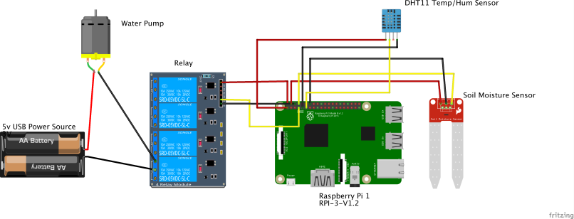
Now you’re ready to start wiring up your components! Follow this diagram and make sure you plug in extra male-male wires to the female headers we soldered earlier to connect everything together.
Notice that we used a relay in our circuit as the Raspberry Pi can only safely tolerate input voltages under 3.3V. Therefore, we need to isolate our 5V power supply to avoid any damage to the Pi.
Hardware
Pump
The pump is a submersible water pump, meaning that it must be completely submerged in a water reservoir in order to pump water. Therefore, for this project, you will need to leave out a bowl (or any method for a reservoir) next to the plant at all times.
NOTE: It’s okay to get the wire tips wet as long as none of the water gets on the RPI!
DHT Sensor
The DHT11 temp/hum sensory is a standard sensor that does not need to be in any particular location, besides being in the same environment as your plant. Since temperature and humidity do not vary greatly within a 5 ft radius, it’s okay to just leave the sensor plugged into the RPI and not right next to the plant.
Soil Moisture Sensor
The soil moisture sensor is a standard moisture sensor that outputs a voltage when wet, and none when dry. You can adjust the sensitivity of the sensor with the potentiometer located on the sensor.
Let’s Get Coding!
Before you do anything, make sure you sign up for a free PubNub account so we don’t run into any problems down the road.
Step 1: Enable SSH
Secure Shell protocol (SSH) allows users to remotely access their Raspberry Pi terminals from their computers over wifi. If supplemented with GitHub, users can push code from their computers to a remote repository, SSH into the Pi terminal, and pull the code wirelessly. This allows for a quicker and smoother development process.
To enable SSH on your RPI, follow the simple and quick instructions.
Step 2: Download Device Libraries and Dependencies
While we may have 3 devices, we only need to read analog voltages from 2 of them. The pump only needs to operate on a GPIO switch. Therefore, we only need to pull dedicated device libraries for the Temp/Hum sensor and soil moisture sensor.
NOTE: Remember that these libraries must be installed onto the RPI by SSH-ing into your device and running the commands below.
DHT Temperature Humidity Sensor
In your project’s directory, clone and enter the sensor’s code repository.
git clone https://github.com/adafruit/Adafruit_Python_DHT.git
cd Adafruit_Python_DHT
Install some Python dependencies.
sudo apt-get upgrade
sudo apt-get install build-essential python-dev
Now, install the sensor’s library.
sudo python setup.py install
This should compile the code for the library and install it on your device so any Python program can access the Adafruit_DHT python module.
If you want to quickly test the sensor to see if the sensor works enter these commands:
cd examples
sudo ./AdafruitDHT.py 2302 4
You should see a reading similar to this:
Raspberry Pi GPIO Library
For our submersible pump, we need to operate an output voltage of 1 or 0 from the RPI to turn it on. Conversely, the soil moisture sensor gives the RPI an input voltage 1 or 0, depending on whether it is wet or dry. Both of these functions require the use of the RPI’s GPIO pins.
Since we’ll be coding in Python, it will be useful to install the GPIO Zero library, which will allow us to make simple function calls to activate the pins.
sudo apt install python-gpiozero
Step 3: Build Your App with PubNub Functions
The full code for this project is located in this repository for reference: https://github.com/Cakhavan/IoT_Plant
First, let’s import our libraries and other dependencies to enable the devices and PubNub Functionality
#Device Libraries
import sys
import Adafruit_DHT
from gpiozero import LED, Button
from time import sleep
#PubNub
import pubnub
from pubnub.pnconfiguration import PNConfiguration
from pubnub.pubnub import PubNub
from pubnub.callbacks import SubscribeCallback
from pubnub.enums import PNOperationType, PNStatusCategory
Next, we’ll need to initialize our sensors and pumps to their corresponding RPI pin numbers
#Pump is connected to GPIO4 as an LED
pump = LED(4)
#DHT Sensor (model type 22) is connected to GPIO17
sensor = 22
pin = 17
#Soil Moisture sensor is connected to GPIO14 as a button
soil = Button(14)
NOTICE: Since the pump will need to be sent an output voltage of on or off (like we would typically do with LEDs) we initialize it as an LED instance. Additionally, we initialized the soil moisture sensor as a button for it will send out a continuous input voltage of a 1 (like when holding down a button) when wet.
It will also be a good idea to set some initial conditions for when the program first boots up: a flag variable to toggle the state of the program to Auto mode or Manual mode and turning the pump off when the program boots up.
#flag variable to toggle between Auto and Manual mode
flag = 1
#always make sure the program starts with the pump turned off (conventions are backwards for the pump i.e. .on()=='off' and .off()=='on')
pump.on()
In order to make sure that our IoT Plant can communicate with a client, we need to enable PubNub’s 2-way pub-sub capability. To make sure we can receive messages we need to add a listener to handle the incoming messages and declare a subscription to listen in on a particular channel.
class MySubscribeCallback(SubscribeCallback):
    def status(self, pubnub, status):
        pass
        # The status object returned is always related to subscribe but could contain
        # information about subscribe, heartbeat, or errors
        # use the operationType to switch on different options
        if status.operation == PNOperationType.PNSubscribeOperation \
                or status.operation == PNOperationType.PNUnsubscribeOperation:
            if status.category == PNStatusCategory.PNConnectedCategory:
                pass
                # This is expected for a subscribe, this means there is no error or issue whatsoever
            elif status.category == PNStatusCategory.PNReconnectedCategory:
                pass
                # This usually occurs if subscribe temporarily fails but reconnects. This means
                # there was an error but there is no longer any issue
            elif status.category == PNStatusCategory.PNDisconnectedCategory:
                pass
                # This is the expected category for an unsubscribe. This means there
                # was no error in unsubscribing from everything
            elif status.category == PNStatusCategory.PNUnexpectedDisconnectCategory:
                pass
                # This is usually an issue with the internet connection, this is an error, handle
                # appropriately retry will be called automatically
            elif status.category == PNStatusCategory.PNAccessDeniedCategory:
                pass
                # This means that PAM does allow this client to subscribe to this
                # channel and channel group configuration. This is another explicit error
            else:
                pass
                # This is usually an issue with the internet connection, this is an error, handle appropriately
                # retry will be called automatically
        elif status.operation == PNOperationType.PNSubscribeOperation:
            # Heartbeat operations can in fact have errors, so it is important to check first for an error.
            # For more information on how to configure heartbeat notifications through the status
            # PNObjectEventListener callback, consult <link to the PNCONFIGURATION heartbeart config>
            if status.is_error():
                pass
                # There was an error with the heartbeat operation, handle here
            else:
                pass
                # Heartbeat operation was successful
        else:
            pass
            # Encountered unknown status type

    def presence(self, pubnub, presence):
        pass  # handle incoming presence data

    def message(self, pubnub, message):
        if message.message == 'ON':
        	global flag
        	flag = 1
        elif message.message == 'OFF':
      global flag
      flag = 0
        elif message.message == 'WATER':
        	pump.off()
        	sleep(5)
        	pump.on()


pubnub.add_listener(MySubscribeCallback())
pubnub.subscribe().channels('ch1').execute()
Then, to enable sending out messages, we declare a publisher callback
def publish_callback(result, status):
  pass
Now, we need a method to check whether our sensor is wet or dry. Since we declared our soil sensor as a button, the function call “is_held” just means that we should check to see when the soil sensor is outputting a continuous “1” (is dry).
def get_status():
  #Soil sensor acts as button. is_held == sensor outputting a 1 for dryness
  if soil.is_held:
    print("dry")
    return True
  else:
    print("wet")
    return False
Next, let’s implement the meat of our program. We’re going to need the RPI continuously polling to check sensor data, so let’s implement a continuous while loop:
while True:
We now need to set state conditions that check whether or not the flag variable is a 1 or a 0 (aka in auto mode or manual mode)
if flag == 1:
     #to be implemented
elif flag == 0:
     #to be implemented
Just like we did before, let’s grab data from the DHT sensor and also print it to the terminal
if flag == 1:
     # Try to grab a sensor reading.  Use the read_retry method which will retry up
     # to 15 times to get a sensor reading (waiting 2 seconds between each retry).
     humidity, temperature = Adafruit_DHT.read_retry(sensor, pin)
     DHT_Read = ('Temp={0:0.1f}*  Humidity={1:0.1f}%'.format(temperature, humidity))
     print(DHT_Read)
Now we can publish that data to PubNub for future IoT use. We’re going to publish on a specific channel so let’s publish to something called “ch2” since “ch1” is reserved for listening for the flag variable.
pubnub.publish().channel('ch2').message([DHT_Read]).async(publish_callback) Then check the status of the soil sensor and turn the pump on or off accordingly
wet = get_status()
if wet == True:
    print("turning on")
    pump.off()
    sleep(5)
    print("pump turning off")
    pump.on()
    sleep(1)
else:
    pump.on()
sleep(1)
NOTE: Remember the backwards convention of the .on() and .off() method call
Lastly, let’s implement the manual mode elif condition, which is just making sure the pump is always off
elif flag == 0:
  pump.on()
  sleep(3)
Step 4: How to Upload Your Code
Like we discussed in the previous section on the use of Git, you should always commit your code to your repository and then pull it to your Raspberry Pi. The process always follows this order
1.) Save your code on your computer
2.) Commit it to the cloud using these commands
git add .
git commit -m "updates"
git push
3.) SSH into your RPI and cd into the proper directory
ssh pi@<YOUR IP ADDRESS>
cd <your directory>
4.) Pull the code from the cloud and run it
git pull
python Plant.py
Step 5: Create a Client
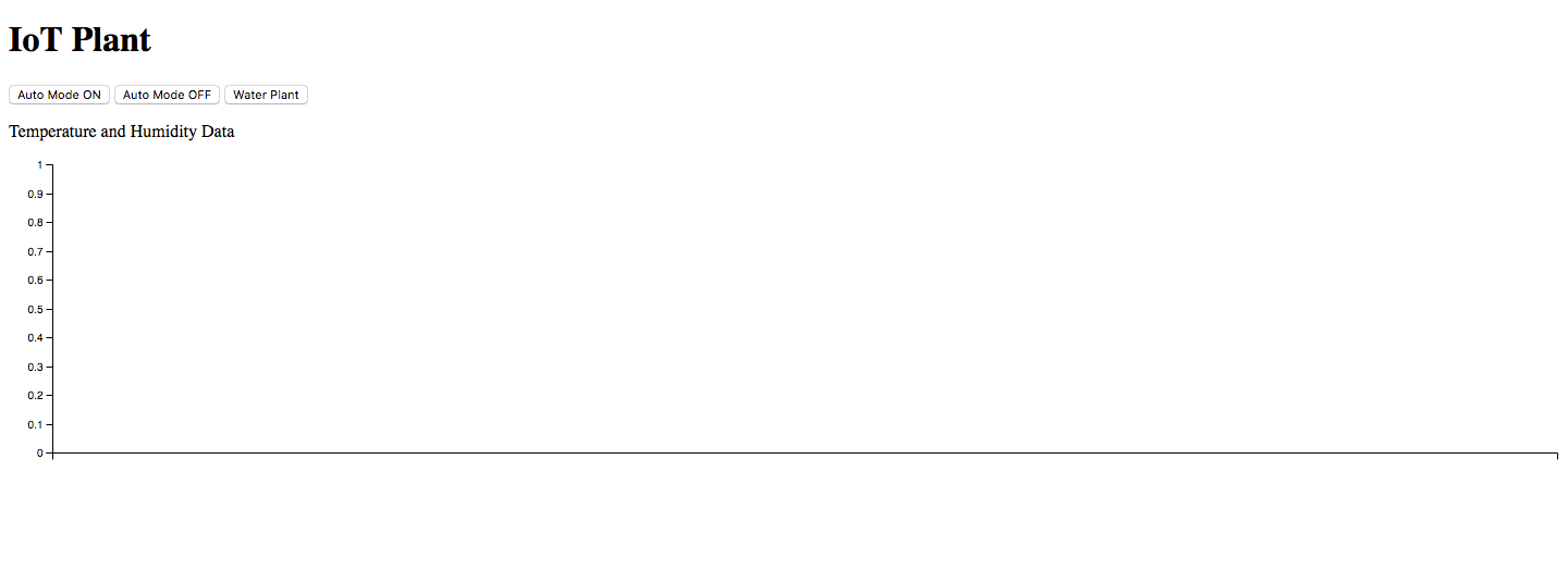
We’re now going to create a front-end HTML page to interact with our IoT plant and later visualize its data in step 6. We will build something that looks like this.
First, let’s start with the 3 buttons that will put the Plant in either the auto state, manual mode state, or water plant state. This will be done by having each button publish a message of which the plant will change its flag variable accordingly.
Let’s first give our page a title
<!DOCTYPE html>
<html>
  <body>
            <h1>IoT Plant</h1>
  </body>
</html>
In the body of your HTML file, insert 3 buttons that publish messages with the PubNub SDK like so
<button type="button" onclick="publish('ON')">Auto Mode ON</button>
<button type="button" onclick="publish('OFF')">Auto Mode OFF</button>
<button type="button" onclick="publish('WATER')">Water Plant</button>
Below those buttons, let’s have our website be continuously updating the screen with the exact temperature humidity data published by the “ch2” channel declared in step 4. In order to do this, we give an id named “sensorData” to a <p> tag so that the program can later inject the content of the <p> tag, using the “getElementByID” and “changeInnerElement” function calls. You’ll see what I’m talking about in a moment.
<p id="sensorData">Temperature and Humidity Data</p>
Now let’s import the PubNub JavaScript SDK in order to actually use that “publish” method and other methods.
<script src="https://cdn.pubnub.com/sdk/javascript/pubnub.4.20.2.js"></script>
Then instantiate a PubNub instance with your API keys
var pubnub = new PubNub({
  publishKey : 'YOUR PUB KEY',
  subscribeKey : 'YOUR SUB KEY',
  });
Then create a publishing call back to publish the button data to the RPI. Notice how we reserved “ch1” for button data and “ch2” for RPI data.
function publish(a){
  var publishConfig =
    {
      channel : "ch1",
      message : a
    };
    pubnub.publish(publishConfig, function(status, response){
      console.log(status, response);
    });

  }
Next, we instantiate a listener and subscriber to get the RPI sensor data. Notice the line that uses the “getElementById” and “innerHTML” function calls introduced earlier. This allows us to take any PubNub message and update any variable on the screen with its respective id tags. This is great for real-time IoT dashboards!
pubnub.addListener({
    message: function(m) {
        // handle message
        var channelName = m.channel; // The channel for which the message belongs
        var channelGroup = m.subscription; // The channel group or wildcard subscription match (if exists)
        var pubTT = m.timetoken; // Publish timetoken
        var msg = m.message; // The Payload
        var publisher = m.publisher; //The Publisher
        //inject the sensor data msg into the sensorData tag declared earlier for real-time updates
        document.getElementById("sensorData").innerHTML = msg;
        console.log(msg)
    },
    presence: function(p) {
        // handle presence
        var action = p.action; // Can be join, leave, state-change or timeout
        var channelName = p.channel; // The channel for which the message belongs
        var occupancy = p.occupancy; // No. of users connected with the channel
        var state = p.state; // User State
        var channelGroup = p.subscription; //  The channel group or wildcard subscription match (if exists)
        var publishTime = p.timestamp; // Publish timetoken
        var timetoken = p.timetoken;  // Current timetoken
        var uuid = p.uuid; // UUIDs of users who are connected with the channel
    },
    status: function(s) {
        var affectedChannelGroups = s.affectedChannelGroups;
        var affectedChannels = s.affectedChannels;
        var category = s.category;
        var operation = s.operation;
    }
});
pubnub.subscribe({
    channels: ['ch2'],

});
Step 6: Graph Your Incoming Data with PubNub EON
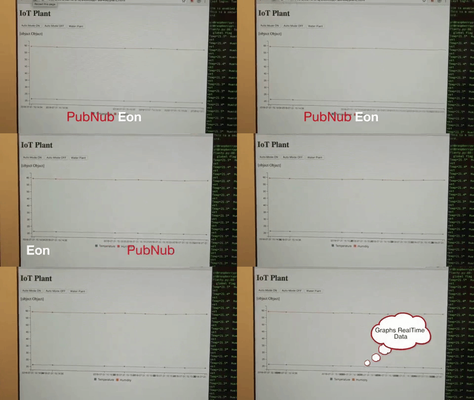
Now comes the flashiest and coolest part of our project: EON! PubNub EON allows users to easily render in a real-time data graph with the drop of a script tag.
By incorporating EON into our project, we’re going to get something that looks like this
HTML Setup
Since at this point you most likely have your HTML page opened up, let’s start implementing EON there first.
To add PubNub EON to any HTML page, simply add this div tag in your body, which will inject the actual chart
<div id="chart"></div>
Then import the script tag SDK
<script type="text/javascript" src="https://pubnub.github.io/eon/v/eon/1.0.0/eon.js"></script>
<link type="text/css" rel="stylesheet" href="https://pubnub.github.io/eon/v/eon/1.0.0/eon.css"/>
Then subscribe to the eon-chart channel that you will be posting data to
eon.chart({
        channels: ['eon-chart'],
        history: true,
        flow: true,
        pubnub: pubnub,
        generate: {
          bindto: '#chart',
          data: {
            labels: false
          }
        }
      });
And that’s it! It’s as simple as that!
Now, let’s implement the last step, which is formatting the sensor’s publisher so EON knows how to graph the data.
Python Setup
This part is even easier. It’s just two lines!
Go back to your Plant.py python code. Now, to publish correctly in python to the eon-chart API correctly, you need to create a dictionary of this type
dictionary = {"eon": {"DATA NAME": DATA, "DATA 2 NAME": DATA 2 etc...}} So in our case, our dictionary would look like this
dictionary = {"eon": {"Temperature": temperature, "Humidity": humidity}} Paste this in right above the line that publishes our sensor data to ch2.
Now we need to publish this dictionary to a channel that our graph is going to read from. In our case, the eon-chart channel.
pubnub.publish().channel("eon-chart").message(dictionary).async(publish_callback)
And there you go! You have successfully created a self-sustaining system for preserving life FOREVER…..until you need to refill the reservoir.


