In this tutorial, we’ll combine the power of a Raspberry Pi board with the sleek functionality of an Android UI. That’s right, we’ll create our own remote configured Raspberry Pi hue LED that can be turned on and off, and change colors, controlled from an Android device.
Before we proceed, I recommend you take a look at the other Raspberry Pi tutorials that PubNub offers. This blog post assumes that you have your Raspberry Pi setup and have the PubNub Python SDK installed. If you do not, check out Raspberry Pi 101 to catch up. If you have your Pi OS up and running, use this tutorial which just gets the PubNub Python SDK installed on your device.
The entire code repository is available here.
Required Hardware
- Raspberry Pi
- Breadboard
- RGB LED Light*
- 3 (~330 Ohm) Resistors
- 4 Male/Female Wires
*Not all LEDs are the same, see Part 1 below:
Part 1. Intro to RGB
Not all RGB LEDs are created equal. They can have a shared cathode, or shared anode.
In the common cathode LED, if only the R pin goes high, the light will show red. However, in the common anode LED, if only the R pin goes high, the light will show Cyan. For those of you who skipped that day of middle school art class, green and blue light together make cyan.
This tutorial will be written for an RGB LED using a common anode. I will point out the blocks of code that will need to be different when using a common cathode. Read about your LED before proceeding.
Part 2. The Setup
2.1 GPIO Pin Selection
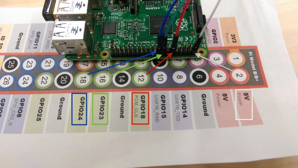
I built my Raspberry Pi Hue using the Raspberry Pi Model B+. You will have to find which pins you want to use, as well as which pin is the 5V power source. If you are using the Model B+ or Model B, you can mimic the picture.
You will need to select 3 GPIO pins. Write down the numbers of the pins you select, we will need them in the next step. In this photo, and for the rest of the demo, I will use colored wires that correspond to the same RGB values on the LED (red wire goes to the pin on the LED corresponding with red). The white wire, in this tutorial, is connected to the 5V power supply. If you are using a common cathode the white wire should go to Ground. Connect the female ends of your Male/Female wires to the pins you selected.
2.2 Breadboard Setup
Now you have your GPIO pins and 5V power source selected and connected. Time to set up the breadboard.
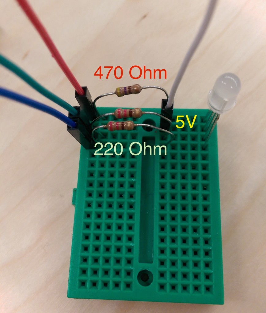
Refer to the RGB LED diagram above again. Notice that the longest wire gets the 5V. You can tell which pin is red since it is on the side of that long pin that only has one pin, not two. From there you can figure out green and blue, they are on the other side of the long pin. In the photo above, the long pin is in the second row from the top, with the white wire.
Time for the resistors.
I said you will need ~300 Ohms, but notice that I use two different resistors. You can play around with what combination works best for you, but as a rule of thumb, the red light tends to overpower the green and blue, so I put a stronger resistor to reduce the current it receives. When we get our light on in the next step, I will show you how to set it to white. If you notice that the “white” looks a little red, you can change the resistor then.
Regardless of a common anode or cathode RGB, you can set up the breadboard exactly as it appears in this photo. The only difference would be what the female end of the white wire is connected to.
Part 3. The Raspberry Pi Code
PubNub offers a C/C++ library and a Python library to use on Raspberry Pi. I implemented this tutorial in Python. If you missed my earlier advice and still need to install the PubNub Python SDK on your Pi, use this tutorial. If you’re ready, then let’s get started!
3.1 Imports and Pin Setup
| #!/usr/bin/python | |
| import time | |
| import RPi.GPIO as GPIO | |
| from pubnub import Pubnub |
These are all the imports you will need. RPi.GPIO allows you to map the pins on your Pi. We will use time and PubNub. Time to coordinate color changes in our LED, and PubNub to stream color values to your Raspberry Pi Hue light.
Remember those pin assignments you wrote down earlier, now we need them.
| ## Make your pin assignments | |
| red_gpio = 18 | |
| green_gpio = 23 | |
| blue_gpio = 24 |
Then we will instantiate our pins using the function GPIO.setup. We need to declare the General Purpose Input/Output pins as either an input or an output.
| ## Setup GPIO Board and Pins | |
| GPIO.setmode(GPIO.BCM) # BCM for GPIO numbering | |
| GPIO.setup(red_gpio, GPIO.OUT) | |
| GPIO.setup(green_gpio, GPIO.OUT) | |
| GPIO.setup(blue_gpio, GPIO.OUT) |
The GPIO.setmode function tells python what pin numbering system is being used. See this thread for a brief description of the options. The GPIO diagram I used to select pin numberings used the BCM channel design.
If you later have issues with this portion, try using the GPIO.BOARD option. GPIO.setup is where we declare the pins as input or output. The other option is of course GPIO.IN which is used when something like a sensor is returning data to the Pi.
| ## Init the GPIO PWMs | |
| Freq = 100 #Hz | |
| RED = GPIO.PWM(red_gpio, Freq) | |
| RED.start(0) | |
| GREEN = GPIO.PWM(green_gpio, Freq) | |
| GREEN.start(0) | |
| BLUE = GPIO.PWM(blue_gpio, Freq) | |
| BLUE.start(0) |
This code is used for setting up your pins using Pulse Width Modulation. PWM is a method for generating an analog signal using a digital source. It encodes a message into a pulsing signal. The “message” in this case, is the RGB values that each of our pins will be sending to the LED.
3.2 The Lighting Code
These pulsing values (on-time and off-time) are called a PWMs Duty Cycle, so the Python function we will be using to set RGB values is <COLOR>.ChangeDutyCycle(<value>).
| # Update the hue with R G B values | |
| def updateHue(R, G, B): | |
| rVal = 100 - (R/255.0)*100 # Will have to change these values depending on | |
| gVal = 100 - (G/255.0)*100 # whether your LED has a common cathode or common | |
| bVal = 100 - (B/255.0)*100 # anode. This code is for common anode. | |
| print "rgb(%.2f, %.2f, %.2f)" % (rVal, gVal, bVal) | |
| RED.ChangeDutyCycle(rVal) | |
| GREEN.ChangeDutyCycle(gVal) | |
| BLUE.ChangeDutyCycle(bVal) |
Since our PWM is pulsing at 100Hz, we must give it a value between 0.0 and 100.0 for its Duty Cycle. 100.0 means the pin always stays high, 0.0 means it always stays low. As anyone who has worked with CSS knows, color values are often represented by 6-digit Hex values. To fit RGB values into 6 digits of hex, each color actually has 2^8 = 256 possible choices (0-255). That said, we now need to find the proportional value of our desired RGB out of 100. For example, a given R value out of 100 is (R/255.0)*100.
This part is especially different for common anode and common cathode LEDs!
If you are using a common cathode (meaning the long pin is connected to Ground), you should use the code rVal = (R/255.0)*100. However, if you are using a common anode (5V to long pin), like me, you will need to use rVal = 100 - (R/255.0)*100
| rVal = (R/255.0)*100 # Common Cathode (Ground) | |
| rVal = 100 - (R/255.0)*100 # Common Anode (5V) |
Think of it this way, Ground is low, 5V is high. If the long pin is going to Ground, you will need the RGB values to go high and give the LED power. If I want the light red, I want to send a rVal of 100.0. If the long pin is connected to the 5V, I am effectively resisting the 5V current by sending currents from the GPIO pins. If I want the common anode light to show red, I want rVal of 0.0 (no resistance on the red current) and a gVal and bVal of 100.0 to resist both of those color currents.
3.3 Quick Test and Debug
You have everything connected now, so let’s run a quick test to make sure that everything is working.
| def rgb(): | |
| updateHue(255,0,0); time.sleep(2) | |
| updateHue(0,255,0); time.sleep(2) | |
| updateHue(0,0,255); time.sleep(2) |
This function will set the light to RED -> GREEN -> BLUE for 2 seconds each. Let’s make a quick main function and run it.
| def main(): | |
| rgb() | |
| updateHue(0,0,0); # Light off | |
| main() |
Save this file as PHue.py Then open the terminal on your pi and cd into the working directory. Then run your python program.
$ cd <project-dir>
$ sudo python PHue.py
You should see your light flash in the order RED -> GREEN -> BLUE. You may have to change the board layout or if you realize they flash in a different order you may have it wired slightly incorrectly. Make sure it goes Red then Green then Blue though, we cannot properly mix colors unless all pins are working correctly.
Do not continue unless it does exactly this.
If you made it this far take a deep breath, the hard part is over and you have successfully wired and programmed a RGB LED, pretty cool!
3.4 Streaming Data
In order to start streaming data to your Raspberry Pi Hue light, you will need a publish and subscribe key. To get your pub/sub keys, you’ll first need to sign up for a PubNub account. Once you sign up, you can find your unique PubNub keys in the PubNub Developer Dashboard. The free Sandbox tier should give you all the bandwidth you need to build and test PHue lightbulb.
Once you have those, you will need to subscribe to a channel. Adding the following lines of code to your main function will accomplish this.
| def main(): | |
| ... | |
| # Instantiate Pubnub | |
| pubnub = Pubnub(publish_key = 'your-pub-key', | |
| subscribe_key = 'your-sub-key') | |
| # This is the channel your Pi will be listening on for RGB values | |
| channel = 'phue' | |
| # This callback handles any messages received on subscribed channel | |
| def _callback(msg, n): | |
| print(msg) | |
| updateHue(msg["RED"], msg["GREEN"], msg["BLUE"]) | |
| def _error(m): | |
| print(m) | |
| pubnub.subscribe(channels=channel, callback=_callback, error=_error) |
First, we create an instance of PubNub, all this requires is your publish and subscribe keys from your dashboard. Then we decide what channel we want out Pi to subscribe to. In order to subscribe you need a channel to listen in on, a callback that will be called when a message is received, and an error callback that will be triggered if any problems are encountered.
Take a look at out callback. The message we receive will be in JSON format, and it will have three fields, RED, GREEN, and BLUE. For example the message we receive for white light may look like this:
{'RED':255, 'GREEN':255, 'BLUE':255}
So long as the JSON object we stream to the Pi has those three fields, we can now send hues from any of PubNubs 70+ SDKs, controlling it from anywhere.
Part 4. An Example in Android
I will now briefly cover an overview of how I created an Android interface for the PHue lightbulb. It will let you select any RGB color for your light to show. The RGB LED I used was surprisingly accurate!
4.1 The Software Setup
I do all my Android development in Android Studio, which is built on JetBrains’ great Java IDE, IntelliJ. If you don’t use it, I believe most of these steps will be similar in Eclipse, but I recommend checking it out.
If you ever get confused, the full PHue Light with Android UI code repo can be found here. My home package is me.kevingleason.phue so adjust what I say according to your package structure. If you want to, feel free to clone my Github Repository then simply update main/java/me/kevingleason/phue/MainActivity.java and change the PUBLISH_KEY and SUBSCRIBE_KEY variables to your pub/sub keys.
Open your IDE and create a New Android Project that uses a blank activity, name the activity MainActivity. I usually use Minimum SDK 15 (That’s the Android Studio default, and I run API 21). This should create the following (relative to the src folder):
build.gradle        # Declare dependencies and Configurations here
main/java/me/kevingleason/phue/MainActivity.java    # Main Activity
main/res/                           # Images and Styles go here
main/res/layout/activity_main.xml   # Your Activity layout goes here
main/AndroidManifest.xml            # You declare your Activities and Permissions here
4.2 Downloading the Packages using Gradle
Downloading PubNub for your project can be done using gradle. Find the dependencies{ ... } section of your build.gradle and add compile 'com.pubnub:pubnub:3.7.3'.
| dependencies { | |
| compile fileTree(dir: 'libs', include: ['*.jar']) | |
| compile 'com.pubnub:pubnub:3.7.3' | |
| } |
4.3 Building the Android UI
Now let’s do some layout!
Start with defining some colors that we can use, like RGB. Create the file main/res/values/colors.xml and define red, green, and blue in it.
| <?xml version="1.0" encoding="utf-8"?> | |
| <!-- colors.xml --> | |
| <resources> | |
| <color name="red">#FFFF0000</color> | |
| <color name="green">#00FF00</color> | |
| <color name="blue">#0000FF</color> | |
| </resources> |
Not let’s make some predefined strings that out layout will use. Go edit main/res/values/strings.xml.
| <?xml version="1.0" encoding="utf-8"?> | |
| <!-- main/res/values/strings.xml --> | |
| <resources> | |
| <string name="app_name">PHue</string> | |
| <string name="hello_world">Hello world!</string> | |
| <string name="action_settings">Settings</string> | |
| <string name="on_button">ON</string> | |
| <string name="off_button">OFF</string> | |
| </resources> |
Beautiful. Now edit main/res/values/styles.xml. We are just going to create some predefined styles that our layout will use.
| <resources> | |
| <!-- main/res/values/styles.xml --> | |
| <!-- Base application theme. --> | |
| <style name="AppTheme" parent="android:Theme.Holo.Light.DarkActionBar"> | |
| <!-- Customize your theme here. --> | |
| </style> | |
| <!-- This is the container or RGB values --> | |
| <style name="AppTheme.RGB"> | |
| <item name="android:layout_width">0dp</item> | |
| <item name="android:layout_height">match_parent</item> | |
| <item name="android:layout_weight">1</item> | |
| <item name="android:gravity">center</item> | |
| <item name="android:textSize">40sp</item> | |
| <item name="android:textStyle">bold</item> | |
| </style> | |
| <!-- The seek bar slider styles --> | |
| <style name="AppTheme.SeekBar"> | |
| <item name="android:layout_width">match_parent</item> | |
| <item name="android:layout_height">wrap_content</item> | |
| <item name="android:padding">25dp</item> | |
| </style> | |
| <!-- The on and off button styles --> | |
| <style name="AppTheme.Button"> | |
| <item name="android:layout_width">0dp</item> | |
| <item name="android:layout_height">match_parent</item> | |
| <item name="android:layout_weight">1</item> | |
| <item name="android:background">#000</item> | |
| <item name="android:textSize">20sp</item> | |
| <item name="android:textColor">#fff</item> | |
| </style> | |
| </resources> |
Now you’re high in style.
Finally, we can create our layout. This is my main/res/layout/activity_main.xml
| <LinearLayout xmlns:android="http://schemas.android.com/apk/res/android" | |
| xmlns:tools="http://schemas.android.com/tools" android:layout_width="match_parent" | |
| android:layout_height="match_parent" | |
| tools:context=".MainActivity" | |
| android:orientation="vertical"> | |
| <LinearLayout | |
| android:layout_width="match_parent" | |
| android:layout_height="72dp"> | |
| <Button | |
| android:onClick="lightOn" | |
| style="@style/AppTheme.Button" | |
| android:text="@string/on_button"/> | |
| <ImageButton | |
| android:src="@drawable/phue" | |
| android:scaleType="centerCrop" | |
| style="@style/AppTheme.Button"/> | |
| <Button | |
| android:onClick="lightOff" | |
| style="@style/AppTheme.Button" | |
| android:text="@string/off_button"/> | |
| </LinearLayout> | |
| <SeekBar | |
| android:id="@+id/red_seek" | |
| style="@style/AppTheme.SeekBar" | |
| android:background="@color/red" /> | |
| <SeekBar | |
| android:id="@+id/green_seek" | |
| style="@style/AppTheme.SeekBar" | |
| android:background="@color/green" /> | |
| <SeekBar | |
| android:id="@+id/blue_seek" | |
| style="@style/AppTheme.SeekBar" | |
| android:background="@color/blue" /> | |
| <LinearLayout | |
| android:id="@+id/rgb_value_holder" | |
| android:layout_width="match_parent" | |
| android:layout_height="match_parent"> | |
| <TextView | |
| android:id="@+id/red_value" | |
| android:textColor="@color/red" | |
| android:text="255" | |
| style="@style/AppTheme.RGB"/> | |
| <TextView | |
| android:id="@+id/green_value" | |
| android:textColor="@color/green" | |
| android:text="255" | |
| style="@style/AppTheme.RGB"/> | |
| <TextView | |
| android:id="@+id/blue_value" | |
| android:textColor="@color/blue" | |
| android:text="255" | |
| style="@style/AppTheme.RGB"/> | |
| </LinearLayout> | |
| </LinearLayout> |
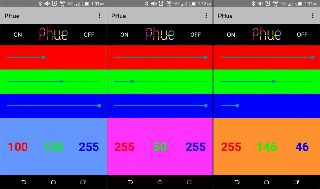
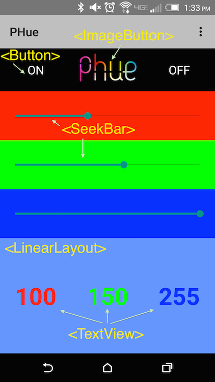
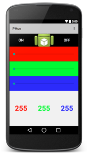
Ideally, you will have something that looks a little like this:
If you want to change what the icon in the top center is, you can put any png or jpg file in main/res/drawable/ folder and change the android:src="@drawable/ic_launcher" of our ImageButton to android:src="@drawable/<your_image>" without the file extension (to refer to my_logo.jpg, use my_logo).
4.4 Permissions
We need to add a few lines to our main/AndroidManifest.xml to get internet permissions. You activity should already be declared here.
| <?xml version="1.0" encoding="utf-8"?> | |
| <manifest xmlns:android="http://schemas.android.com/apk/res/android" | |
| package="me.kevingleason.phue" > | |
| <uses-permission android:name="android.permission.INTERNET" /> | |
| <uses-permission android:name="android.permission.ACCESS_NETWORK_STATE" /> | |
| <uses-permission android:name="android.permission.ACCESS_WIFI_STATE" /> | |
| <uses-permission android:name="com.google.android.c2dm.permission.RECEIVE" /> | |
| ... | |
| </manifest> |
Thats all, you have my permission to continue.
4.5 Code – The Dynamic Part
Luckily this app only have one activity, and as such I kept all code in one file. It is usually best practice to house constants in a Config or Util file, but for a tutorial I felt better keeping it all centralized.
The full Java code can be found here. Use it to follow along, I will try to step you through the pieces.
| package me.kevingleason.phue; | |
| import android.app.Activity; | |
| import android.os.Bundle; | |
| import android.util.Log; | |
| import android.view.Menu; | |
| import android.view.MenuItem; | |
| import android.view.MotionEvent; | |
| import android.view.View; | |
| import android.widget.LinearLayout; | |
| import android.widget.SeekBar; | |
| import android.widget.TextView; | |
| import com.pubnub.api.Callback; | |
| import com.pubnub.api.Pubnub; | |
| import com.pubnub.api.PubnubError; | |
| import org.json.JSONException; | |
| import org.json.JSONObject; | |
| public class MainActivity extends Activity { | |
| public static final int COLOR_RED = 0; // Arbitrary ID's | |
| public static final int COLOR_BLUE = 1; // that are used | |
| public static final int COLOR_GREEN = 2; // later in the code | |
| SeekBar mRedSeek, mGreenSeek, mBlueSeek; // All our layout pieces | |
| LinearLayout mRGBValueHolder; // that we will be editing | |
| // Pubnub instance and all the keys you will need to stream data | |
| private Pubnub mPubNub; | |
| public static final String PUBLISH_KEY = "your-pub-key"; | |
| public static final String SUBSCRIBE_KEY = "your-sub-key"; | |
| public static final String CHANNEL = "phue"; | |
| private long lastUpdate = System.currentTimeMillis(); // Used to thereshold | |
| ... | |
| } |
This just instantiates all your views that you declared in your layout, all the values you will need to stream data with PubNub, and then some values that we will use as utility throughout the program.
Now for the backbone of every activity, the onCreate function.
| @Override | |
| protected void onCreate(Bundle savedInstanceState) { | |
| super.onCreate(savedInstanceState); | |
| setContentView(R.layout.activity_main); | |
| // Instantiate PubNub. We will cover this shortly. | |
| initPubNub(); | |
| // Get Seek Bars. They will be at R.id.<your-seekbar-id> | |
| mRedSeek = (SeekBar) findViewById(R.id.red_seek); | |
| mGreenSeek = (SeekBar) findViewById(R.id.green_seek); | |
| mBlueSeek = (SeekBar) findViewById(R.id.blue_seek); | |
| mRGBValueHolder = (LinearLayout) findViewById(R.id.rgb_value_holder); | |
| // Setup Seek Bars. We will cover this function shortly. | |
| setupSeekBar(mRedSeek, COLOR_RED); | |
| setupSeekBar(mGreenSeek, COLOR_GREEN); | |
| setupSeekBar(mBlueSeek, COLOR_BLUE); | |
| } |
We will do the initPubNub and setupSeekBar functions next. Those functions are made to setup our seek bars as well as get pub nub ready to stream data. The only other thing this function does is assign our instance variable views to their proper location in the XML layout.
initPubNub()
Instantiating PubNub in Android is simple. This is all the initPubNub function looks does:
| public void initPubNub(){ | |
| this.mPubNub = new Pubnub( | |
| PUBLISH_KEY, | |
| SUBSCRIBE_KEY | |
| ); | |
| this.mPubNub.setUUID("AndroidPHue"); | |
| subscribe(); | |
| } |
I give the PubNub instance my pub/sub keys, and set the Unique User ID to “Android PHue”. I then call subscribe to subscribe me to CHANNEL.
subscribe()
| public void subscribe(){ | |
| try { | |
| this.mPubNub.subscribe(CHANNEL, new Callback() { | |
| @Override | |
| public void successCallback(String channel, Object message) { | |
| Log.d("PUBNUB","SUBSCRIBE : " + channel + " : " | |
| + message.getClass() + " : " + message.toString()); | |
| } | |
| }); | |
| } catch (Exception e) { | |
| e.printStackTrace(); | |
| } | |
| } |
There are a lot of functions that have to be implemented for subscribe to work, all different kinds of callbacks. All I am having my callbacks here do is print the error or message.
setupSeekBar(SeekBar seek, int colorID)
We have 3 SeekBars to program, so why not make one function that does it instead of having code redundancies. This is why we created those arbitrary color id class variables (e.g. COLOR_RED).
| public void setupSeekBar(SeekBar seekBar, final int colorID){ | |
| seekBar.setMax(255); // Seek bar values goes 0-255 | |
| seekBar.setProgress(255); // Set the knob to 255 to start | |
| seekBar.setOnSeekBarChangeListener(new SeekBar.OnSeekBarChangeListener() { | |
| @Override | |
| public void onStopTrackingTouch(SeekBar seekBar) { | |
| publish(mRedSeek.getProgress(), mGreenSeek.getProgress(), mBlueSeek.getProgress()); | |
| } | |
| @Override | |
| public void onStartTrackingTouch(SeekBar seekBar) { | |
| publish(mRedSeek.getProgress(), mGreenSeek.getProgress(), mBlueSeek.getProgress()); | |
| } | |
| @Override | |
| public void onProgressChanged(SeekBar seekBar, int progress, | |
| boolean fromUser) { | |
| TextView colorValueText; | |
| switch (colorID){ // Get the TextView identified by the colorID | |
| case COLOR_RED: | |
| colorValueText = (TextView)findViewById(R.id.red_value); | |
| break; | |
| case COLOR_GREEN: | |
| colorValueText = (TextView) findViewById(R.id.green_value); | |
| break; | |
| case COLOR_BLUE: | |
| colorValueText = (TextView)findViewById(R.id.blue_value); | |
| break; | |
| default: | |
| Log.e("SetupSeek","Invalid color."); | |
| return; | |
| } | |
| colorValueText.setText(String.valueOf(progress)); // Update the 0-255 text | |
| int red = mRedSeek.getProgress(); // Get Red value 0-255 | |
| int green = mGreenSeek.getProgress(); // Get Grn value 0-255 | |
| int blue = mBlueSeek.getProgress(); // Get Blu value 0-255 | |
| updateRGBViewHolderColor(red, green, blue); // Change the background of the viewholder | |
| long now = System.currentTimeMillis(); // Only allow 1 pub every 100 milliseconds | |
| if (now - lastUpdate > 100 && fromUser) { // Threshold and only send when user sliding | |
| lastUpdate = now; | |
| publish(red, green, blue); // Stream RGB values to the Pi | |
| } | |
| } | |
| }); | |
| } |
This just finds the TextView that corresponds to the color of the SeekBar. Then the main logic happens in the onProgressChanged. What to do every time Android detects that the SeekBar value has been changed (perhaps if the user dragged one of the knobs).
You must update the TextView that corresponds to that SeekBar, update the background for a pretty effect with updateRGBViewHolderColor and then if it has been more than 100ms since your last publish, we send the data to the Pi via Pubnub. It is also important to publish when we start moving the slider onStartTrackingTouch and when we lift our finger from the slider onStopTrackingTouch.
updateRGBViewHolderColor()
This function is fun, mostly because I always enjoy using bitwise operators.
| private void updateRGBViewHolderColor(int red, int green, int blue){ | |
| int alpha = 255; // No opacity | |
| int color = (alpha << 24) | (red << 16) | (green << 8) | blue; | |
| mRGBValueHolder.setBackgroundColor(color); | |
| } |
This creates the proper color combination. Since each value of RGB has 2^8 possible options, we must shift each value over by some factor of 8 so none of the bits are overwritten. We also bitwise or (|) with the alpha value. If you wanted to make a solid white color, the proper android color is #FFFFFFFF. That gives values of Alpha FF, Red FF, Green FF, and Blue FF, since FF in hex is 255. From the XML, or in CSS, the FF alpha value is assumed, but in code we must add it. Once we build our color, we set the background color of our view holder.
publish(int red, int blue, int green)
Publish the current red, blue, and green values. As we stated earlier our Pi is just waiting for something of the form {'RED':255, 'GREEN':255, 'BLUE':255}, and in Java we can make that using a JSONObject
| public void publish(int red, int green, int blue){ | |
| JSONObject js = new JSONObject(); | |
| try { | |
| js.put("RED", red); | |
| js.put("GREEN", green); | |
| js.put("BLUE", blue); | |
| } catch (JSONException e) { e.printStackTrace(); } | |
| Callback callback = new Callback() { | |
| public void successCallback(String channel, Object response) { | |
| Log.d("PUBNUB",response.toString()); | |
| } | |
| }; | |
| this.mPubNub.publish(CHANNEL, js, callback); | |
| } |
PubNub uses JSONObject to send messages. If you remember from earlier, the only values we need are RED, GREEN, and BLUE. Once we set these values we have to create callbacks much like we did for the raspberry pi, then call the Pubnub object’s publish function.
And there you have it. Your PHue lightbulb!
From here you can just add the simple little functions with ease, since all your code is fairly modular right now. setRGBSeeks just updates the positions of the RGB SeekBar knobs.
| public void setRGBSeeks(int red, int green, int blue){ | |
| mRedSeek.setProgress(red); | |
| mGreenSeek.setProgress(green); | |
| mBlueSeek.setProgress(blue); | |
| } |
We can then make an on and off button as follows:
| public void lightOff(View view){ | |
| publish(0, 0, 0); // 0,0,0 is black or OFF | |
| setRGBSeeks(0, 0, 0); | |
| } | |
| public void lightOn(View view){ | |
| publish(255, 255, 255); // 255,255,255 is White or ON | |
| setRGBSeeks(255, 255, 255); | |
| } |
Extending the Tutorial
That is the full featured app.
However, PubNub is more powerful that just simple data streams. There are functions to store state-data for a channel, monitor presence changes, or see who is currently subscribed to your channel. Let’s say we wanted to make the RGB view our Android device black when there was no light connected. We could accomplish that by first modifying the initPubNub function.
| public void initPubNub(){ | |
| this.mPubNub = new Pubnub( | |
| PUBLISH_KEY, | |
| SUBSCRIBE_KEY | |
| ); | |
| this.mPubNub.setUUID("AndroidPHue"); | |
| hereNow(); // Check if any light is on the channel before you join | |
| subscribe(); | |
| } |
Then implementing the hereNowfunction as follows.
| public void hereNow(){ | |
| this.mPubNub.hereNow(CHANNEL, new Callback() { | |
| @Override | |
| public void successCallback(String channel, Object response) { | |
| Log.d("PUBNUB", response.toString()); | |
| try { | |
| JSONObject json = (JSONObject) response; | |
| if (json.getInt("occupancy") == 0){ | |
| setRGBSeeks(0,0,0); | |
| MainActivity.this.runOnUiThread(new Runnable() { | |
| @Override | |
| public void run() { | |
| Toast.makeText(MainActivity.this,"No Light Detected.", Toast.LENGTH_LONG).show(); | |
| // Do something to views... | |
| } | |
| }); | |
| } | |
| } catch (JSONException e){ e.printStackTrace(); } | |
| } | |
| @Override | |
| public void errorCallback(String channel, PubnubError error) { | |
| Log.d("PUBNUB", error.toString()); | |
| } | |
| }); | |
| } |
This calls the Pubnub#hereNow(String channel) function, converts the response to a JSONObject, checks the occupancy, and makes the RGB view black if no devices are subscribed. PubNub spawns threads to accomplish tasks, hence it uses Callbacks. In order to access views from a thread, you need to use MainActivity.this.runOnUiThread(Runnable runnable), and modify view properties (or create Toast) from there.
That’s all I have for you this time! Notice that I made the center button (between on and off) and ImageButton. You can make this button do anything you want with your PHue, see if you can get creative!

